Redrawing diagrams

This forum made possible through the generous support of SDN members, donors, and sponsors. Thank you.

SaintJude

Full Member
10+ Year Member
Joined
Jan 4, 2012
Messages
1,479
Reaction score
5
I'm really glad I did this problem, b/c I got it wrong.

Don't look on the next post--it's the answer. Does anyone know a good site to practice these?

Kaplan:
A student connected the following circuit. S1, S2 and S3 are switches that can be closed to make electrical connection. The resistors are rated at the following values: R1*=*R2*=*R3*=*R6 =*10*Ω, R4*=*R5 = 20*Ω. Unless otherwise indicated, the battery can be assumed to be ideal (no internal resistance).

59637.64.h020355img01.gif


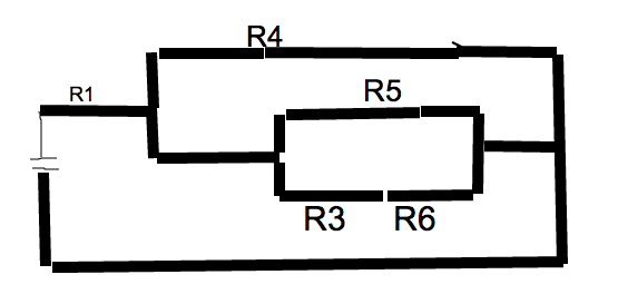
What is the total effective resistance when all switches are closed?

Members don't see this ad.
 
I don't really know of a good site, but all I did to answer this was start from the battery and work my way down thinking to myself; "R1 and R4 are in series, but are in parallel with R2 and R5, which are in series with each other..." and so on.

There aren't any more problems like that in Kaplan?
 
I don't really know of a good site, but all I did to answer this was start from the battery and work my way down thinking to myself; "R1 and R4 are in series, but are in parallel with R2 and R5, which are in series with each other..." and so on.

There aren't any more problems like that in Kaplan?

yes, but the important realization is that R4 alone is parallel with R2 and R2. Not both R1 and R4.

how do we determine, systematically, what is in parallel and in series with such a diagram?
 
Members don't see this ad :)
yes, but the important realization is that R4 alone is parallel with R2 and R2. Not both R1 and R4.

how do we determine, systematically, what is in parallel and in series with such a diagram?


Please help! I thought I was ok with electricity (I studied TPR), but this has totally destroyed my confidence. I don't understand how it can be 20. At first glance I assumed (incorrectly, it seems) that R1 and R4 are in series (R2 and R5; also R3 and R6) and then these three "groups" are in parallel to each other. However, that is not the case, since the shape of the diagram forces the current to go through one group before the other...so I am very unclear on how to "group" these in order to calculate the resistance. Can somebody walk me through it slowly?
 
Second time around, I got it right, just had to redraw it right.

So, do this:

The bottom two will become 20. Do a R1*R2 / R1+R2 at the bottom: it becomes 10. It's in series with a 10, so it becomes 20. Repeat, repeat, to get 20 overall.

I did not know 1 and 4 were in series until I redrew it and I only got it right after MedPR's post.
 
Last edited:
Please help! I thought I was ok with electricity (I studied TPR), but this has totally destroyed my confidence. I don't understand how it can be 20....Can somebody walk me through it slowly?

Every time you hit a junction, draw a "fork in the road". Try testing if you understand this w/o looking at my picture below. So begin by tracing the current's path as it moves from the voltage point. As the current moves slightly beyond R1, it hits a junction. Stop. Draw a fork.

One path will move to R4 and the other moves on to R2. Since R2 looks more "complicated" let's continue the current's path as it move on to R2. Again, as the current moves slightly beyond R2, it hits a junction. Stop. Draw a fork.

One path will lead to a R5 and the other will lead to R3 AND R6 (R6 is in series w/R3 b/c there's no junction). Now complete the circuit noting that the path of R6 and R5 seems to end at the same junction point.

So, once I understood how to do it, my picture actually looks different from Kaplan's but that's just b/c Kaplan used a variation in drawing the circuit. But the result is the same.

Edit: forgot to label R2. It directly precedes the junction to R5 & R3

hNBe9.png
 
Last edited:
Every time you hit a junction, draw a "fork in the road". Try testing if you understand this w/o looking at my picture below. So begin by tracing the current's path as it moves from the voltage point. As the current moves slightly beyond R1, it hits a junction. Stop. Draw a fork.

One path will move to R4 and the other moves on to R2. Since R2 looks more "complicated" let's continue the current's path as it move on to R2. Again, as the current moves slightly beyond R2, it hits a junction. Stop. Draw a fork.

So, once I understood how to do it, my picture actually looks different from Kaplan's but that's just b/c Kaplan used a variation in drawing the circuit. But the result is the same.

Edit: forgot to label R2. It directly precedes the junction to R5 & R3

hNBe9.png

Wow! Thank you for that walk-through. That is exactly what I needed. I had to draw it out and really think to get this one. I sure hope there is nothing like this on the real MCAT, because it consumes too much time redrawing/rethinking everything. Incredible!
 
Top