You are using an out of date browser. It may not display this or other websites correctly.
You should upgrade or use an alternative browser.
You should upgrade or use an alternative browser.
AAMC SB C/P Q17
- Thread starter arc5005
- Start date

- Joined
- Jun 17, 2014
- Messages
- 63,099
- Reaction score
- 154,727
A voltmeter is used to measure the voltage difference between two different points but it should not change the amount of current flowing between those two points (i.e. the voltmeter should not draw any current). So an ideal voltmeter should have infinite resistance and draw zero current. Chapter 16 Concepts
From the problem, we see the following circuit diagram:
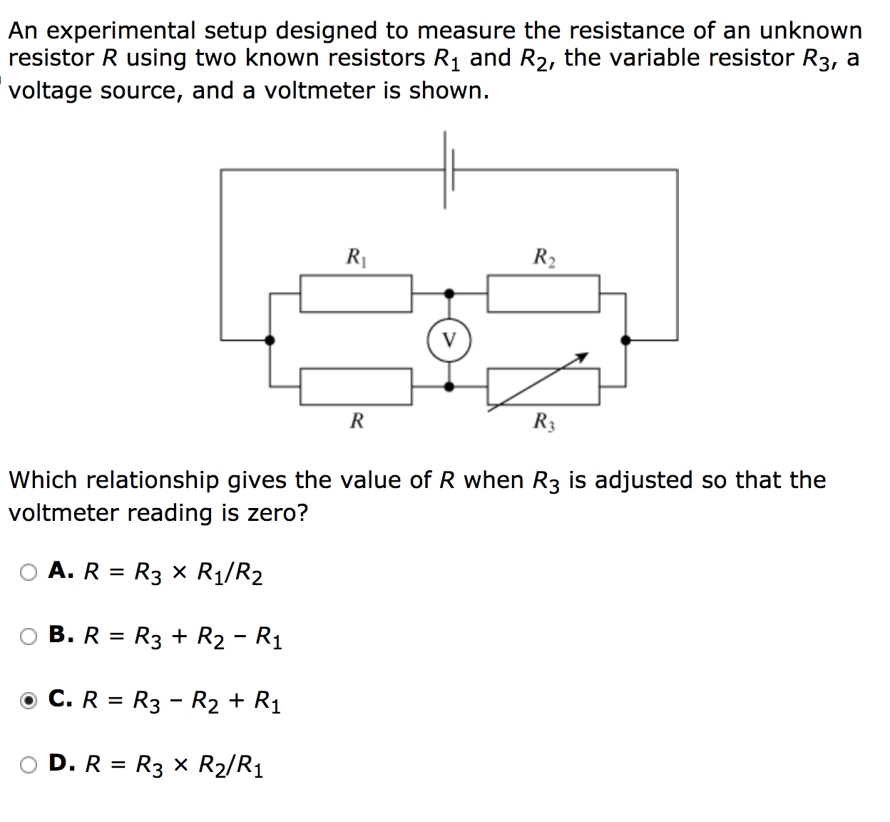
The voltmeter helps visualize dividing this circuit into two smaller circuits. Because the voltmeter reading is zero, each of the smaller circuit has zero total voltage.
First take a look at the left smaller circuit. Let’s call the current flowing through R1 as I1 and the current flowing through R as I. By Ohm’s Law (V = IR), the voltage across R1 is I1 * R1 and the voltage across R is I * R. These voltages should add up to zero since the voltmeter reading is zero. This happens when I * R = I1 * R1 (so the voltage across R should equal the voltage across R1).
The current I1 flowing through R1 also flows through R2 without change because the voltmeter has infinite resistance and does not draw any current. Likewise, the current I flowing through R also flows through R3 without change. Since the total voltage at the right smaller circuit is zero, I1 * R2 = I * R3.
So this means:
I * R = I1 * R1 —>
R = I1/I * R1;
I1 * R2 = I * R3 —>
I1/I = R3 / R2;
R = R3/R2 * R1
This looks like a difficult problem since it can be readily solved by using Kirchhoff’s circuit laws, which is not in the AAMC content guidelines. For more information, see: Kirchhoff's laws
From the problem, we see the following circuit diagram:
The voltmeter helps visualize dividing this circuit into two smaller circuits. Because the voltmeter reading is zero, each of the smaller circuit has zero total voltage.
First take a look at the left smaller circuit. Let’s call the current flowing through R1 as I1 and the current flowing through R as I. By Ohm’s Law (V = IR), the voltage across R1 is I1 * R1 and the voltage across R is I * R. These voltages should add up to zero since the voltmeter reading is zero. This happens when I * R = I1 * R1 (so the voltage across R should equal the voltage across R1).
The current I1 flowing through R1 also flows through R2 without change because the voltmeter has infinite resistance and does not draw any current. Likewise, the current I flowing through R also flows through R3 without change. Since the total voltage at the right smaller circuit is zero, I1 * R2 = I * R3.
So this means:
I * R = I1 * R1 —>
R = I1/I * R1;
I1 * R2 = I * R3 —>
I1/I = R3 / R2;
R = R3/R2 * R1
This looks like a difficult problem since it can be readily solved by using Kirchhoff’s circuit laws, which is not in the AAMC content guidelines. For more information, see: Kirchhoff's laws
- Joined
- Feb 8, 2018
- Messages
- 67
- Reaction score
- 24
Oh is this a wheatstone bridge?
Oh is this a wheatstone bridge?
I believe so yes, because I've come across other problems similar to this AAMC SB question that had this setup but was actually called a "wheatstone bridge"
A voltmeter is used to measure the voltage difference between two different points but it should not change the amount of current flowing between those two points (i.e. the voltmeter should not draw any current). So an ideal voltmeter should have infinite resistance and draw zero current. Chapter 16 Concepts
From the problem, we see the following circuit diagram:
The voltmeter helps visualize dividing this circuit into two smaller circuits. Because the voltmeter reading is zero, each of the smaller circuit has zero total voltage.
First take a look at the left smaller circuit. Let’s call the current flowing through R1 as I1 and the current flowing through R as I. By Ohm’s Law (V = IR), the voltage across R1 is I1 * R1 and the voltage across R is I * R. These voltages should add up to zero since the voltmeter reading is zero. This happens when I * R = I1 * R1 (so the voltage across R should equal the voltage across R1).
The current I1 flowing through R1 also flows through R2 without change because the voltmeter has infinite resistance and does not draw any current. Likewise, the current I flowing through R also flows through R3 without change. Since the total voltage at the right smaller circuit is zero, I1 * R2 = I * R3.
So this means:
I * R = I1 * R1 —>
R = I1/I * R1;
I1 * R2 = I * R3 —>
I1/I = R3 / R2;
R = R3/R2 * R1
This looks like a difficult problem since it can be readily solved by using Kirchhoff’s circuit laws, which is not in the AAMC content guidelines. For more information, see: Kirchhoff's laws
Thank you. While I understand what you're saying, I'm not sure I'd be able to replicate the algebra correctly in a timed setting if a similar problem as this one came up. It seems fairly complicated in regards to how much time I generally have available for each question on the C/P section. I'll check out the link for kirchhoff's laws. thank you again!
- Joined
- Jun 17, 2014
- Messages
- 63,099
- Reaction score
- 154,727
I believe so yes, because I've come across other problems similar to this AAMC SB question that had this setup but was actually called a "wheatstone bridge"
Thank you. While I understand what you're saying, I'm not sure I'd be able to replicate the algebra correctly in a timed setting if a similar problem as this one came up. It seems fairly complicated in regards to how much time I generally have available for each question on the C/P section. I'll check out the link for kirchhoff's laws. thank you again!
Section Bank problems are harder than the real deal. It's good practice to understand difficult concepts but I wouldn't worry about the math too much.